Introduction to OpenGL
Part 6: Advanced concepts
In this part we will be introduced to some advanced OpenGL techniques that will spice up our scenes. Apart from learning these techniques our main goal is to see how they can make our applications a little more interesting and eye-catching.
For example, how can we implement the rear-view mirror of a car, or even how can we see through a keyhole or a glass window? In the previous part we were introduced in the use of light, but light casts shadows, how do we deal with them?
Stencil Buffers
We are starting our exploration of the special effects with Stencil Buffers.
In graphic arts one of the most used tools is the stencil. This tool allows us to draw a pattern by applying ink or paint. It might be one of the oldest drawing tools ever used. The most common application of a stencil in prehistoric times was the human hand on the walls of the caves, where people painted around their hands.
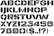
This idea evolved, and now we have created tools that allow us to draw from simple text to complex patterns, using the same principle. By cutting out specific shapes on a piece of paper, we can create a simple stencil with letters as we see in this figure.
OpenGL has a similar mechanism we can use to keep our drawing inside any shape.
What we do is create a canvas, or stencil buffer in technical terms, the size of the screen. Then we cut out the openings that allow the paint to pass and finally we draw. Here is a description of how we do it.
As you may have noticed in the beginning of our drawing function we clear the screen
glClear (GL_COLOR_BUFFER_BIT | GL_DEPTH_BUFFER_BIT | GL_STENCIL_BUFFER_BIT);As you can see in this case we have added a third option, the GL_STENCIL_BUFFER_BIT which clears the stencil canvas as well and initializes it to screen size. The stencil buffer is typically initialized to black. Everything we draw on it is done in white and that marks the cut outs that will enable us to create the stencil we will use on our scene.
Using stencil buffers is a four-step process as opposed to normal drawing which is a one step process.
- First we enable writing to the stencil buffer.
- Then we draw our stencil shape.
- Third we enable normal drawing.
- Finally we draw our scene.
The stencil sample demonstrates this technique, where we can see a rotating cube through a moving window.
virtual void frame_render() {
    // set the viewport to the whole window
    m_view->set_viewport();

    // GL_STENCIL_BUFFER_BIT  needs mask=0xFF
    glStencilMask(0xff);
    glClear(GL_COLOR_BUFFER_BIT | GL_DEPTH_BUFFER_BIT | GL_STENCIL_BUFFER_BIT);

    // we are using stencil
    glEnable(GL_STENCIL_TEST);
    // prepare the stencil buffer
    glColorMask(GL_FALSE, GL_FALSE, GL_FALSE, GL_FALSE);
    glDepthMask(GL_FALSE);
    glStencilFunc(GL_NEVER, 1, 0xFF);
    glStencilOp(GL_REPLACE, GL_KEEP, GL_KEEP);  // draw 1s on test fail (always)

    // draw stencil pattern
    m_shader->use();
    mat4 ob_matrix;
    ob_matrix.loadIdentity();  // at the center of the screen
    m_shader->set_mat4("model", ob_matrix);
    m_shader->set_mat4("camera", ob_matrix);
    // move the window
    m_shader->set_vec3("displacement", vec3(xcen, ycen, 0));
    // disabling these to speed up drawing
    glDisable(GL_CULL_FACE);
    glDisable(GL_DEPTH_TEST);
    pstencil->render(NULL);

    // return to normal drawing
    glColorMask(GL_TRUE, GL_TRUE, GL_TRUE, GL_TRUE);
    glDepthMask(GL_TRUE);
    glStencilMask(0x00); // do NOT draw on black
    // draw only where stencil's value is 1
    glStencilFunc(GL_EQUAL, 1, 0xFF);
    // enable them before we start normal draing
    glEnable(GL_CULL_FACE);
    glEnable(GL_DEPTH_TEST);

    // stop moving around
    m_shader->set_vec3("displacement", vec3(0, 0, 0));
    // and proceed with normal drawing
    mat4 cam_matrix = m_cam->perspective() * m_view->perspective();
    m_light->apply(m_shader);
    m_shader->set_mat4("camera", cam_matrix);
    m_shader->set_vec3("cameraPos", m_cam->vLocation);

    // draw a rectangle behind the cube to act as background
    // this will make the stecil shape visible
    m_shader->set_vec3("objectColor", vec3(0.75f, 0.85f, 0.85f));
    pbackgound->render(m_shader);
    // and now draw the cube
    m_shader->set_vec3("objectColor", vec3(.1f, .2f, .9f));
    m_cube->render(m_shader);
    // stop using stncil
    glDisable(GL_STENCIL_TEST);
    glUseProgram(0);
}
Blending
With blending in OpenGL we mean the mixing of colors, like when we see through a colored glass or a semitransparent medium. This is the case when we see the world through our sunglasses, for example.
Applying glass color is quite common in virtual reality simulation and everyday practice in games.
The technique is quite simple, and the results are sometimes spectacular. So let us start demystifying it.
We will start with the object's material. We will not use the materials from the previous chapter but only the object's color, to keep things simple and focus only on what is important.
The color of the object can have a fourth component, apart from the red, green, and blue, we used so far. This is usually referred to as alpha channel or transparency. An opaque material has the value of 1 and a fully transparent has the value 0. Real world objects have values anywhere between these limits.
Drawing with blending is simple but it requires some work on our side. It must be done in a specific order to achieve the desired and correct results.
First we upgrade our color to have four components adding the opacity in the alpha channel. So, our color variable for the objects' colors are now of type vec4 instead of vec3. Then we start drawing all our opaque objects. In our sample this is a spinning cube.
When we are done with the opaque objects, we draw our transparent objects. This is the process we will analyze more because here is where all the magic happens.
Our transparent objects must be ordered starting from the farthest and finishing to the closest to the viewer, and then be drawn in that order. All color calculations required for blending are performed as we pass the objects to the pipeline, and drawing order really makes a difference.
We can use texture images as textures for our transparent objects. This is a lot more flexible than using a color value for the entire surface. We can add a byte per pixel in the target image, as the alpha channel, and encode in it 256 different levels of opacity. This can give our object varying opacity over its area. We see this in our example as the blue 'glass' changes from completely opaque to completely transparent. It is combined with a red uniform glass to show how two transparent objects can be combined.
virtual void frame_render() {
    // set the viewport to the whole window
    m_view->set_viewport();
    glClearColor(0.2f, 0.2f, 0.2f, 1);
    glClear(GL_COLOR_BUFFER_BIT | GL_DEPTH_BUFFER_BIT);

    m_shader->use();
    m_light->apply(m_shader);
    // set the texture we will use
    glActiveTexture(GL_TEXTURE0);
    glBindTexture(GL_TEXTURE_2D, texture);

    mat4 cam_matrix = m_cam->perspective() * m_view->perspective();
    m_shader->set_mat4("camera", cam_matrix);
    m_shader->set_vec3("cameraPos", m_cam->vLocation);

    // draw opaque objects first
    m_shader->set_vec4("objectColor", vec4(0, 1, 0, 1));
    // use object color parameter, do not look for texture
    m_shader->set_int("useColor", 1);
    m_cube->render(m_shader);

    // start blending
    glEnable(GL_BLEND);
    glBlendFunc(modes[source_mode], modes[dest_mode]);
    // and now transparent objects (sorted)
    if (draw_order == 0)
    {
        // ignore object color and use texture
        m_shader->set_int("useColor", 0);
        pglass->move_to(vec3(0, 0, -1.5f));
        pglass->render(m_shader);

        m_shader->set_vec4("objectColor", vec4(.9f, .1f, .1f, 0.5f));
        m_shader->set_int("useColor", 1);
        pglass->move_to(vec3(0, 0, 0));
        pglass->render(m_shader);
    }
    else
    {
        m_shader->set_vec4("objectColor", vec4(.9f, .1f, .1f, 0.5f));
        m_shader->set_int("useColor", 1);
        pglass->move_to(vec3(0, 0, -1.5f));
        pglass->render(m_shader);

        m_shader->set_int("useColor", 0);
        pglass->move_to(vec3(0, 0, 0));
        pglass->render(m_shader);
    }
    glBindTexture(GL_TEXTURE_2D, 0);
    // stop blending
    glDisable(GL_BLEND);

    glUseProgram(0);

    // the following will be analyzed in the next chapter
    font2D->set_position(5, 35);
    font2D->render("source:%s, destination:%s", mode_names[source_mode].c_str(), mode_names[dest_mode].c_str());
    font2D->set_position(5, 20);
    font2D->render("press M/N to change draw mode");
    font2D->set_position(5, 5);
    font2D->render("press D to change draw order");
}
As we said before the color of the incoming fragment is combined with the color of the corresponding fragment in the frame buffer.
The following equation is applied.
Where source is the output of the fragment shader, and dest is the content of the frame buffer. The Factor is calculated according to the parameters given to the glBlendFunc.
| Option | Factor is equal to |
|---|---|
| GL_ZERO | 0 |
| GL_ONE | 1 |
| GL_SRC_COLOR | Colorsource |
| GL_ONE_MINUS_SRC_COLOR | (1,1,1,1) - Colorsource |
| GL_DST_COLOR | Colordest |
| GL_ONE_MINUS_DST_COLOR | (1,1,1,1) - Colordest |
| GL_SRC_ALPHA | (Asource, Asource, Asource, Asource) |
| GL_ONE_MINUS_SRC_ALPHA | (1,1,1,1) - (Asource, Asource, Asource, Asource) |
| GL_DST_ALPHA | (Adest, Adest, Adest, Adest) |
| GL_ONE_MINUS_DST_ALPHA | (1,1,1,1) - (Adest, Adest, Adest, Adest) |
You can experiment with the blending options and see how OpenGL handles it. Blending in OpenGL is not difficult. There is only one thing to remember. Never break the order of execution:
- Render opaque objects.
- Render transparent objects sorted according to their distance from the viewer.
Face culling
The number of faces in 3D applications increases as the available computation power increases. The situation is getting worse as the complexity of the scene increases. The system has to perform all those tasks required raising the barrier even higher. If OpenGL could easily identify which faces are actually facing away from the screen it could completely ignore them while drawing and speed the rest of the drawing process dramatically.
We know that a great part of the surface of a solid object is invisible to us. The part that faces away from us, the back of the object as we call it. The viewer never sees those faces, and they usually measure more than 50% of the total number of faces we must draw in our scene.
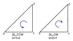
There is an easy way to define if a face is pointing towards the viewer. We will use a simple triangle to illustrate the method. As you can see in this figure, we can define the triangle issuing its vertices in a counter clock or clockwise manner. If we define all our triangles consistently, then the triangles in the back facing surfaces will be drawn the opposite way due to the space transformation. This is a clear sign that we can skip them.
We can 'tell' OpenGL which rotation is front facing and which is back facing, as well as which is to be omitted from drawing. I prefer to define counterclockwise as the positive rotation because it follows the right-hand rule which I find helpful when setting up the calculations for my application. The basic rule is to be consistent, and you can follow any rule you feel more comfortable with.
To achieve back face culling is easy. We start by enabling the feature in OpenGL.
glEnable(GL_CULL_FACE);Then we define which rotation faces front, and which we want to draw, front facing, back facing or both. GL_CCW is for counterclockwise and GL_CW is for clockwise
glFrontFace(GL_CCW);
glPolygonMode(GL_FRONT, draw_mode);
The benefit of using this technique in small programs like the samples of this book is negligible. As the points and faces count increases though it makes a huge difference.
Cubemap / Skybox
Cubemaps simplify the texture we can apply on a cube, hence the name cubemap. It is an easy way to draw the distant horizon, the sky above and the earth below.
Imagine yourself being in a huge cubic box, the faces of which display carefully selected images of the surrounding environment, creating a panorama of whatever is around us.
These are the steps we need to follow to create a cubemap.
The first step is to generate a texture, just like any other texture by calling the glGenTextures function.
Then we must activate this texture by binding it with glBindTexture. Here is the first difference from ordinary textures. Instead of using the GL_TEXTURE_2D parameter, we use the GL_TEXTURE_CUBE_MAP. This is used in all the texture functions we use for the cubemap.
The next step is to load the images. Loading the images has no new feature to talk about. After loading the images, we store them in OpenGL using glTexImage2D. The first parameter of this function is one of the cube face ids. Let me explain this in more detail.
The first value defined in OpenGL is GL_TEXTURE_CUBE_MAP_POSITIVE_X. This means that the corresponding image will be used for the face lying on the YZ plane and has positive X coordinate.
The five other values are GL_TEXTURE_CUBE_MAP_NEGATIVE_X, GL_TEXTURE_CUBE_MAP_POSITIVE_Y, GL_TEXTURE_CUBE_MAP_NEGATIVE_Y, GL_TEXTURE_CUBE_MAP_POSITIVE_Z, GL_TEXTURE_CUBE_MAP_NEGATIVE_Z, mapping the other five faces.
At the end we have created a texture with six layers, as referred to in OpenGL documentation. Each layer has an ID based on its location and is assigned a texture image.
The coordinate system for cubemaps used internally by OpenGL is left-handed. So positive X points to the RIGHT, positive Y points UP, and positive Z points from the viewer to the screen. On the other hand, our game engine uses a right-handed coordinate system. This combination creates a problem when displaying cubemaps. The textures are rotated by 180° and left and right are swapped. To fix this we rotate the images after we have loaded them, and we swap the left and right images.
Here is the code that loads the texture images for the cubemap.
void cg_skybox::load(const std::vector<std::string>& faces)
{
    if (skyboxVAO == 0)
    {
        // cg_skybox VAO
        glGenVertexArrays(1, &skyboxVAO);
        glGenBuffers(1, &skyboxVBO);
        glBindVertexArray(skyboxVAO);
        glBindBuffer(GL_ARRAY_BUFFER, skyboxVBO);
        glBufferData(GL_ARRAY_BUFFER, sizeof(skyboxVertices), &skyboxVertices, GL_STATIC_DRAW);
        glEnableVertexAttribArray(0);
        glVertexAttribPointer(0, 3, GL_FLOAT, GL_FALSE, 3 * sizeof(float), (void*)0);
    }

    if (default_shader == NULL)
    {
        default_shader = new cg_shader;
        default_shader->compile(vertex_source, fragment_source);
    }

    glGenTextures(1, &textureID);
    glBindTexture(GL_TEXTURE_CUBE_MAP, textureID);

    for (auto i = 0; i < 6; i++)
    {
        cg_image* img = new cg_image;
        img->load(faces[i].c_str());
        // the coordinate system for cubemaps is left-handed
        // and the coordinate system of our engine is right-handed
        // so we rotate the images by 180 degrees
        img->rotate180();
        glTexImage2D(GL_TEXTURE_CUBE_MAP_POSITIVE_X + i, 0, img->format(),
            img->width(), img->height(), 0, img->format(), GL_UNSIGNED_BYTE, img->image());
        delete img;
    }

    glTexParameteri(GL_TEXTURE_CUBE_MAP, GL_TEXTURE_MIN_FILTER, GL_LINEAR);
    glTexParameteri(GL_TEXTURE_CUBE_MAP, GL_TEXTURE_MAG_FILTER, GL_LINEAR);
    glTexParameteri(GL_TEXTURE_CUBE_MAP, GL_TEXTURE_WRAP_S, GL_CLAMP_TO_EDGE);
    glTexParameteri(GL_TEXTURE_CUBE_MAP, GL_TEXTURE_WRAP_T, GL_CLAMP_TO_EDGE);
    glTexParameteri(GL_TEXTURE_CUBE_MAP, GL_TEXTURE_WRAP_R, GL_CLAMP_TO_EDGE);
}
The naming and coordinate convention we need to follow when we use the underlying engine to draw a skybox is as follows.
| Coordinate macro | Relative position |
|---|---|
| GL_TEXTURE_CUBE_MAP_POSITIVE_X | Right |
| GL_TEXTURE_CUBE_MAP_NEGATIVE_X | Left |
| GL_TEXTURE_CUBE_MAP_POSITIVE_Y | Up |
| GL_TEXTURE_CUBE_MAP_NEGATIVE_Y | Down |
| GL_TEXTURE_CUBE_MAP_POSITIVE_Z | Front |
| GL_TEXTURE_CUBE_MAP_NEGATIVE_Z | Back |
Our cubemap texture is now ready. The next thing we are going to analyze is the drawing of the skybox. We expect drawing to be easy, after all this is the reason we use this technique.
And it is easy to use the skybox. To begin with all we need is the vertex coordinates. No texture mapping coordinates or vertex normal are required. Since our object is a simple cube and the texture maps directly to the vertices of each face, OpenGL can easily choose the correct image and mapping based on the vertex coordinates alone.
The other thing we need is the location and orientation of the camera, the point in space we are looking to, and the angle of our field of view. In other words, the view and camera matrices. We should note here that we removed the positioning part from the camera matrix. This is done because we are placing our viewer in the center of the cube, which is supposed to be big.
The viewer matrix defines the view vector which is used by OpenGL to determine the fragment of the texture to render. It will automatically select the image or layer to use and apply all the necessary transformations. The shader code is in the cg_skybox.cpp file for easier installation of the engine and the samples.
// vertex shader
#version 330 core

layout(location = 0) in vec3 aPos;
layout(location = 1) in vec3 aNormal;
layout(location = 2) in vec2 aTexCoord;

uniform mat4 camera;
uniform mat4 model;

out vec3 Normal;
out vec3 pos;
out vec2 texCoord;

// nothing unusual in the vertex shader
void main() {
    gl_Position = camera * model * vec4(aPos, 1);
    pos = vec3(model * vec4(aPos, 1));
    Normal = mat3(transpose(inverse(model))) * aNormal;
    texCoord = aTexCoord;
}
// fragment shader
#version 330 core

uniform int useColor;       // use color=1 or texture=0
uniform vec4 objectColor;   // object color to use
uniform vec3 cameraPos;     // viewer location
uniform samplerCube skybox; // skybox texture

in vec3 Normal;             // surface normal
in vec3 pos;                // drawing position

out vec4 color;             // resulting drawing color

void main() {
    // used when drawing text
    if (useColor == 1) {
        color = objectColor;
    }
    // used for textured objects
    else {
        // calculate reflection and not direct view
        vec3 view = normalize(pos - cameraPos);
        // reflect is a builtin function in GLSL
        vec3 reflection = reflect(view, normalize(Normal));
        // the reflection vector determines the output color
        color = vec4(texture(skybox, reflection).rgb, 1.0);
    }
}
Environment mapping
We can dramatically improve our drawing and make it more realistic if we calculate the reflections of the environment onto the surfaces of our objects. The technique is called raytracing, and it is a simulation of whatever happens in nature.
Unfortunately, this is a very computationally intensive technique, and complex scenes take too long to render. Even with state-of-the-art hardware, the rendering speed is not good for gaming or any other real-time application.
One technique to help us achieve equally great results is Environment mapping. In this we create reflections of texture images on the surfaces we want. This is very efficient since all the light effects are precalculated and encoded in the texture image.
This technique complements the skybox we saw before. Instead of rendering the images on the surrounding cube, we render their reflections on the objects in the scene. The reflections can be rendered even if we do not draw the skybox.
We just set up the texture as we do in the skybox and then with the help of our shaders we calculate the reflections on the objects. In the sample code (cubemap.cpp) you can comment out the rendering of the skybox and still see it rendered on the objects.
To use environment mapping we create a skybox and use its texture. The skybox class contains all the code required to load the texture images and then use them to generate OpenGL textures.
All the work is done in the shader and more precisely in the fragment shader. In the vertex shader we perform the usual calculations we did in when we had to apply light and texture. Both shaders were presented in the previous section Cubemap / Skybox
In the fragment shader on the other hand, we calculate the vector from the camera position to fragment position and calculate its reflection on the surface with the help of the normal vector. The reflected vector points to the location on the skybox and that is where we get the color to render.
The reflection is calculated by the reflect function which is a built-in function in GLSL. It takes two arguments, the vector to be reflected and the normal vector of the surface at the reflection point.
Frame buffers
According to the official definition, a Frame buffer in OpenGL is a buffer that can be used as the destination for rendering. There are two types of frame buffers. First is the default frame buffer, which we have used so far for rendering, and the user-created frame buffer which is usually called Frame Buffer Object or FBO for short.
You may wonder why we need frame buffers and what we can do with them. Well, consider the following situation. Somewhere in your game scene there is a television which is on, playing some animation. Using a frame buffer can help you create that effect. You can render the animation using a frame buffer and then use that buffer as a texture for the television screen when rendering the main scene. The frame buffer is a live texture!
As is the case with all the OpenGL tools we have seen so far, a frame buffer must be created before we can start using it. You can view the frame buffer as a painter's canvas on which we can draw and then hang it on our wall as a piece of art that decorates our scene.
Here is the code that creates the frame buffer.
unsigned int cg_texture_buffer::create(int w, int h)
{
    glGenFramebuffers(1, &m_buffer);
    glBindFramebuffer(GL_FRAMEBUFFER, m_buffer);
    // create a color attachment texture
    glGenTextures(1, &m_texture);
    glBindTexture(GL_TEXTURE_2D, m_texture);
    glTexImage2D(GL_TEXTURE_2D, 0, GL_RGB, w, h, 0,
                               GL_RGB, GL_UNSIGNED_BYTE, NULL);
    glTexParameteri(GL_TEXTURE_2D, GL_TEXTURE_MIN_FILTER, GL_LINEAR);
    glTexParameteri(GL_TEXTURE_2D, GL_TEXTURE_MAG_FILTER, GL_LINEAR);
    glFramebufferTexture2D(GL_FRAMEBUFFER, GL_COLOR_ATTACHMENT0, GL_TEXTURE_2D, m_texture, 0);
    glBindFramebuffer(GL_FRAMEBUFFER, 0);
    return m_buffer;
}
You will notice the great resemblance between this and the creation of other objects we have seen so far. In this case we create a frame buffer and then we create a texture which we attach to the frame buffer. Something like setting a frame and a canvas.
After its creation we can leave the frame buffer until we need to draw on it. When that time comes we must call the glBindFramebuffer function passing the buffer ID like this:
glBindFramebuffer(GL_FRAMEBUFFER, m_buffer);From that point on all our drawing is redirected to the frame buffer. To stop the redirection, we call the same function with a value of 0 as a frame buffer ID. Now the frame buffer contains an image that can be used for anything we want. The most common use is as a texture image somewhere in our program.
virtual void frame_render() {
    // we will draw on an off-screen image, which we will use
    // as a texture for the object we will draw later

    // here we go
    // first we 'redirect' our rendering to the texture buffer
    m_tex_buffer->bind();
    // and we get on with rendering as usual
    glEnable(GL_DEPTH_TEST);
    // set the viewport to the image size
    fb_view->set_viewport();
    // clear the screen
    glClearColor(0.7f, 0.6f, 0.5f, 0.4f);
    glClear(GL_COLOR_BUFFER_BIT | GL_DEPTH_BUFFER_BIT);
    glDepthFunc(GL_LEQUAL);
    m_shader_create->use();
    m_light->apply(m_shader_create);
    mat4 cam_matrix = m_cam->perspective() * fb_view->perspective();
    m_shader_create->set_mat4("camera", cam_matrix);
    m_shader_create->set_vec3("cameraPos", m_cam->vLocation);
    m_shader_create->set_vec3("objectColor", vec3(.4f, .9f, .9f));
    m_cube->render(m_shader_create);
    glUseProgram(0);
    // and finally we stop redirection
    m_tex_buffer->release();

    // and now we use the image as texture and we draw the cube again
    glEnable(GL_DEPTH_TEST);
    // set the viewport to the whole window
    m_view->set_viewport();
    // clear the screen
    glClearColor(0.2f, 0.2f, 0.2f, 1);
    glClear(GL_COLOR_BUFFER_BIT | GL_DEPTH_BUFFER_BIT);
    glDepthFunc(GL_LEQUAL);
    m_shader_use->use();
    m_light->apply(m_shader_use);
    cam_matrix = m_cam->perspective() * m_view->perspective();
    m_shader_use->set_mat4("camera", cam_matrix);
    m_shader_use->set_vec3("cameraPos", m_cam->vLocation);
    m_shader_use->set_int("useColor", 0);
    // set the texture we created
    glBindTexture(GL_TEXTURE_2D, m_tex_buffer->texture());
    m_sphere->render(m_shader_use);
    // release shader
    glUseProgram(0);

    // the following will be analyzed in the next chapter
    m_shader_use->set_int("useColor", 1);
    m_shader_use->set_vec4("objectColor", vec4(.9f, .1f, .1f, 1));
    glUseProgram(0);
    font2D->set_position(5, 5);
    font2D->render("press Esc to exit");
}
The texture object inside the frame buffer class is just like any other image texture we have used so far. All we must do is bind and use it in our drawing.
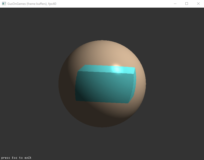
In the example frame_buffer we use two different shaders, one while rendering in the frame buffer and one while rendering the actual scene. A close look at the shader code will make clear that the only reason for this is to demonstrate that they can be two completely different scenes.
In the first part of the rendering function, we draw in the frame buffer a rotating cube. Then in the second part we use that image as a texture for a rotating sphere.
Shadows
We are all familiar with shadows in our everyday life. So far we have learned how to deal with light in our games. We have learned how it reflects on the surfaces of objects and creates all the nice effects. However, our scenes seem empty. Our brain expects the light to cast shadows and when we do not see them we get that strange feeling.
According to the dictionary shadow is the dark figure cast upon a surface by a body intercepting the rays from a source of light. This definition really shows us what to do to get some realistic renderings with shadows.
The best way to calculate shadows is the technique called raytracing. In this method we trace the rays of light and simulate the effect they have when they hit an object. This way we can generate all the shininess and reflection we have seen so far. This automatically generates shadows since the areas the light cannot reach remain unlit.
Raytracing is the method of choice for high quality rendering and modern graphic cards provide specialized hardware to assist calculations. However, it is still far from becoming the mainstream technique for games or real time simulation applications.
You see ray-tracing algorithms are very computationally intensive and the time needed for a scene to render is too long compared to the time available in our applications. Here we should add the very expensive hardware needed for these cutting edge technologies.
To overcome these problem and still have realistic scenes other techniques have been proposed and are used by game developers. The technique used by the most video games is shadow mapping. This is an easy to understand and implement technique, as well as fast with great results. All these make it an excellent choice for real time applications running on hardware anyone can buy.
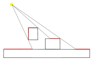
We will start by explaining the idea behind shadow mapping. First look at this figure. The areas marked in red are in the way of light and their color can be calculated as we have seen before. The rest of the surfaces are not lit directly because the light is obscured.
A closer look at this image reveals the actual algorithm on which shadow mapping is based.
In this algorithm we create an image from the light point of view. We imagine our camera is in the position of the light source and it is looking to the direction the light points.
This approach reveals the fragments of the scene that receive direct light. Here comes the real trick. In the frame buffer we store the distance of the fragment from the light source, or our imaginary camera. Every other fragment in that direction is in the shadow.
In the next step we render our scene from our normal point of view, based on our camera. Before deciding the final color of a fragment, we calculate its distance from the light source and compare it with the distance stored in the shadow buffer. If the distance calculated is greater than the distance stored then the fragment is in the shadow and should be treated appropriately.
The approach presented here is a simple one and the light is treated as directional light. This means that we treat all light rays as parallel as the light rays from a very distant light source like the sun and not as rays from a small source nearby where the rays are radial.
The added complexity required for accurate shadow calculations for point light and especially when there is more than one light source belongs in an OpenGL focused book.
Now let us see the details of shadow mapping. As we said first we render our scene in an off-screen buffer. OpenGL provides the type of buffer we need for this purpose. We created a GL_FRAMEBUFFER like we used in the previous section. This time the texture we attach to it has the GL_DEPTH_ATTACHMENT attribute. This instructs OpenGL that we will store distances and not colors. Our game engine has a class called cg_depth_buffer which takes care of the trivial tasks. For our needs, a 1024x1024 pixel buffer is enough. Here is how we create the buffer:
unsigned int cg_depth_buffer::create(int w, int h)
{
    // configure depth map FBO
    glGenFramebuffers(1, &m_buffer);
    glBindFramebuffer(GL_FRAMEBUFFER, m_buffer);

    // create depth texture
    glGenTextures(1, &m_texture);
    glBindTexture(GL_TEXTURE_2D, m_texture);
    glTexImage2D(GL_TEXTURE_2D, 0, GL_DEPTH_COMPONENT, w, h, 0,
                 GL_DEPTH_COMPONENT, GL_FLOAT, NULL);
    glTexParameteri(GL_TEXTURE_2D, GL_TEXTURE_MAG_FILTER, GL_NEAREST);
    glTexParameteri(GL_TEXTURE_2D, GL_TEXTURE_MIN_FILTER, GL_NEAREST);
    glTexParameteri(GL_TEXTURE_2D, GL_TEXTURE_WRAP_S, GL_CLAMP_TO_EDGE);
    glTexParameteri(GL_TEXTURE_2D, GL_TEXTURE_WRAP_T, GL_CLAMP_TO_EDGE);
    // attach depth texture as FBO's depth buffer
    glFramebufferTexture2D(GL_FRAMEBUFFER, GL_DEPTH_ATTACHMENT, GL_TEXTURE_2D,
                           m_texture, 0);
    glDrawBuffer(GL_NONE);
    glReadBuffer(GL_NONE);
    if (glCheckFramebufferStatus(GL_FRAMEBUFFER) != GL_FRAMEBUFFER_COMPLETE)
        m_buffer = 0;
    glBindFramebuffer(GL_FRAMEBUFFER, 0);
    return m_buffer;
}
The 2D texture attribute we use means that this image will be used as a 'texture' at the second stage of our rendering operation. Our rendering function looks like this:
virtual void frame_render()
{
    // create the depth buffer from the light point of view
    mat4 l_projection(ortho(-10, 10, -10, 10, 0.1f, 70.f));
    mat4 l_view(lookAt(m_light->get_position(),vec3(0.0f),vec3(0.0,1.0,0.0)));
    mat4 lightSpaceMatrix(l_projection * l_view);
    // render scene from light's point of view
    depth_shader->use();
    // the projection matrix in light space
    depth_shader->set_mat4("lightSpaceMatrix", lightSpaceMatrix);
    glViewport(0, 0, 1024, 1024);
    d_buffer->bind();
    glClear(GL_DEPTH_BUFFER_BIT);
    glCullFace(GL_FRONT);
    // render our scene, we do not need to go into its details here
    render_scene(depth_shader);
    glCullFace(GL_BACK);
    d_buffer->release();

    // --------------------------------------------------------
    // set the viewport to the whole window
    m_view->set_viewport();
    glClearColor(0.2f, 0.2f, 0.2f, 1);
    glClear(GL_COLOR_BUFFER_BIT | GL_DEPTH_BUFFER_BIT);

    m_shader->use();
    m_light->apply(m_shader);

    mat4 projection = m_view->perspective();
    mat4 view = m_cam->perspective();
    m_shader->set_mat4("projection", projection);
    m_shader->set_mat4("view", view);
    // the projection matrix in light space
    m_shader->set_mat4("lightSpaceMatrix", lightSpaceMatrix);

    glActiveTexture(GL_TEXTURE0);
    glBindTexture(GL_TEXTURE_2D, d_buffer->texture());
    m_shader->set_int("shadowMap", 0);
    // render our scene, we do not need to go into its details here
    render_scene(m_shader);

    // the following will be analyzed in the next part
    m_shader->set_vec4("objectColor", vec4(.9f, .1f, .1f, 0.5f));
    font2D->set_position(5, 5);
    font2D->render(m_shader, "press Esc to exit");

    glUseProgram(0);
}
The first part of the function renders the scene from the light point of view like rendering on the screen. Then in the second part we bind the texture we created and render our scene from the player's point of view.
Now we are going to look at the shader code used. We start with the shader we use for the depth buffer. Here we only need the position of the point which is calculated in the vertex shader and stored in the gl_Position predefined variable. The fragment shader can be empty or omitted completely.
#version 330 core
layout(location = 0) in vec3 aPos;

uniform mat4 lightSpaceMatrix;
uniform mat4 model;

void main() {
    gl_Position = lightSpaceMatrix * model * vec4(aPos, 1.0);
}
This builds our depth buffer, and we proceed to our normal rendering where all the magic happens. The vertex shader calculates the final position if the vertex and stores it in gl_Position as usual, but it also calculates the vertex position in the light space as did the depth vertex shader. This light space position will be used to check if the final fragment is in the shadow.
The fragment shader introduces a new function we call shadow_calculation which reads the depth buffer to determine whether the fragment is in the shadow or not.
#version 330 core

in vec3 pos;
in vec3 Normal;
in vec2 TexCoords;
in vec4 posLightSpace;

struct lightsource {
    int type;
    vec3 pos_or_dir;
    vec3 ambient;
    vec3 diffuse;
    vec3 specular;
};
uniform lightsource light;
uniform sampler2D shadowMap;
uniform vec3 cameraPos;
uniform vec3 objectColor; // object color

out vec4 color;
float shadow_calculation(){
    // perform perspective divide
    vec3 projCoords = posLightSpace.xyz / posLightSpace.w;
    // transform to [0,1] range
    projCoords = projCoords * 0.5 + 0.499;
    // get closest depth value from light's perspective
    // (using [0,1] range fragPosLight as coords)
    float closestDepth = texture(shadowMap, projCoords.xy).r;
    // get depth of current fragment from light's perspective
    float currentDepth = projCoords.z;
    // check whether current frag pos is in shadow
    float shadow = currentDepth > closestDepth ? 1.0 : 0.0;

    return shadow;
}

void main(){
    vec3 normal = normalize(Normal);

    vec3 ambient = light.ambient;

    vec3 lightDir = normalize(light.pos_or_dir);
    float diff = max(dot(lightDir, normal), 0.0);
    vec3 diffuse = diff * light.diffuse;

    vec3 viewDir = normalize(cameraPos - pos);
    vec3 reflectDir = reflect(-light.pos_or_dir, normal);
    vec3 halfwayDir = normalize(light.pos_or_dir + viewDir);
    float spec = pow(max(dot(normal, halfwayDir), 0.0), 128.0);
    vec3 specular = spec * light.specular;

    float shadow = shadow_calculation();

    vec3 result = (ambient + (1.0 - shadow)*(diffuse + specular))*objectColor;

    color = vec4(result, 1);
}
You may have noticed that during the creation of the shadow map we called the glCullFace function and inverted which is the face to render. We used this trick to overcome an artifact called shadow acne. This is because the shadow map is made up of samples and the actual surface is continuous. This leads to spots where the shadow function fails, and we end up with black stripes. This trick makes the shadow map more continuous and eliminates the problem.
Fog
Another interesting visual effect that adds a lot of reality and mystery in a game scene is fog. Objects that are far away generally appear less sharp and clear compared to objects that are close by.
Fog involves adjusting the color of a pixel based on its distance from the camera.
It can also enhance the depth perception.
The general implementation is as follows:
- Define the clear color to be your fog color.
- Pass a distance value to the fragment shader in some manner.
- Define fog parameters:
- Minimum distance.
- Maximum distance.
- Fog color – identical to the clear color.
- Fog relationship, e.g., linear or exponential.
- Calculate the fog factor from depth distance (in eye coordinates).
- Ensure the fog factor ranges from 0 (no fog) to 1 (maximum fog):
- The `clamp()` function is useful for this.
- Mix the lit, shaded color with the fog color:
- The `mix()` function is useful for this.
All these calculations are performed in the fragment shader. The fog class passes all the required parameters to the shader in the ‘apply’ member function.
Heightmap
A heightmap enables the creation of intricate landscapes derived from images, often utilizing the same images applied as textures for those landscapes.
How is the information encoded
Images typically consist of three integer values ranging from 0 to 255 for each pixel. These values represent the primary colors—RED, GREEN, and BLUE—allowing for the 16 million colors we commonly see in images.
Now, imagine we have an aerial photograph of a location. It could be useful to encode the 'altitude' or 'elevation' of each point in the image. This is done by adding an additional value for each pixel, known as an extra channel—often referred to as the alpha channel. This new value is another integer between 0 and 255, where 0 represents the lowest altitude and 255 represents the highest altitude.
From image to geometry
When converting image data into geometry data, three key parameters are required. The first is the altitude variation, which determines the height of each pixel by multiplying it with the alpha channel value. The second is the length scale, representing the assumed physical distance between pixels. Since our geometry is grounded in 'real' measurements, this parameter facilitates the transformation of image-based coordinates and data into world coordinates. Lastly, the resolution of the generated grid plays a vital role. This parameter dictates the step size for grid generation, specifying how many pixels to skip at each step.
The whole process is done in two steps.
First we read the height information into a two-dimensional matrix skipping the pixels as we mentioned before. Here is the code that creates this matrix:
// resolution is the number of pixels to skip as we read the image
int load_heightmap_image_matrix(const std::string& filename, matrix<float>& m, int resolution) {
    cg_image img;
    img.load(filename.c_str());

    int rows = img.height();
    int cols = img.width();

    unsigned char* data = img.image();

    if (!data) return 0;

    m.resize(rows/ resolution, cols/ resolution);
    // step is the number of bytes per pixel
    int step = img.bytes_per_pixel();

    for (int r = 0; r < rows; r += resolution) {
        for (int c = 0; c < cols; c += resolution) {
            // read alpha channel
            m(r / resolution, c / resolution) = (data[(r * cols + c) * step + step - 1] / 255.0f);
        }
    }

    return 1;
}
Then we create a triangular mesh for the ground based on this matrix. Every element of the matrix is a point on the terrain with the points having a specific distance between them and the elevation being proportional to the value stored in the matrix. Here is the code that we use to generate the mesh:
c_mesh* create_heightmap_mesh(const matrix<float>& hmap, float length_scale, float height_scale) {
    c_mesh* ms = new c_mesh;
    auto cols = hmap.cols - 1;   // goes into our x direction
    auto rows = hmap.rows - 1;   // goes into our z direction
    // the edges of the terrain
    float minx = -(cols * length_scale) / 2;
    float maxx = (cols * length_scale) / 2;
    float minz = -(rows * length_scale) / 2;
    float maxz = (rows * length_scale) / 2;
    int idx = 0; // counting the number of generated points
    // texture coordinates for the terrain
    float sx = 1.f / cols;
    float sz = 1.f / rows;
    float tx = 0;
    float tz = 0;

    for (auto z = 0; z < rows; ++z)
    {
        tx = 0;
        for (auto x = 0; x < cols; ++x)
        {
            // x and z coordinates
            float x1, x2, z1, z2;
            x1 = minx + x * length_scale;
            x2 = minx + (x + 1) * length_scale;
            z1 = minz + z * length_scale;
            z2 = minz + (z + 1) * length_scale;
            // y coordinates (elevation)
            float y1, y2, y3, y4;
            y1 = hmap(z, x) * height_scale;
            y2 = hmap(z, x + 1) * height_scale;
            y3 = hmap(z + 1, x + 1) * height_scale;
            y4 = hmap(z + 1, x) * height_scale;
            // the four points
            vec3 v1(x1, y1, z1);
            vec3 v2(x2, y2, z1);
            vec3 v3(x2, y3, z2);
            vec3 v4(x1, y4, z2);
            // the first triangle
            ms->addVertex(v1);
            ms->addVertex(v2);
            ms->addVertex(v3);
            ms->addIndices_n(idx + 2, idx + 1, idx + 0);
            // and the texture coordinates
            ms->addTexCoord(tx, tz);
            ms->addTexCoord(tx+sx, tz);
            ms->addTexCoord(tx+sx, tz+sz);
            idx += 3;
            // the second triangle
            ms->addVertex(v1);
            ms->addVertex(v3);
            ms->addVertex(v4);
            ms->addIndices_n(idx + 2, idx + 1, idx + 0);
            // and the texture coordinates
            ms->addTexCoord(tx, tz);
            ms->addTexCoord(tx + sx, tz+sz);
            ms->addTexCoord(tx, tz + sz);
            idx += 3;
            tx += sx;
        }
        tz += sz;
    }
    return ms;
}
All this is managed by this function:
gl_prim* create_heightmap(const std::string& fname, float length_scale, float height_scale, int image_resolution, GLenum drmode, bool dr_el) {
    matrix<float> hmap(1, 1);
    load_heightmap_image_matrix(fname, hmap, image_resolution);
    c_mesh* m_hmap = create_heightmap_mesh(hmap, length_scale, height_scale);
    gl_prim* p = new gl_prim;
    p->create_from_mesh(m_hmap, drmode, dr_el);
    p->set_texture(load_texture(fname));
    delete m_hmap;
    return p;
}
Summary
In this part we covered the basics of OpenGL drawing. Now you are ready to create some nice programs and games, with nice visual effects. So far we have covered:- Stencil buffers that can help us create irregularly shaped drawing areas.
- Blending, to simulate transparency.
- Face culling, to define back and front faces.
- Skyboxes to draw the horizon.
- Environment mapping that reflects the environment on the surfaces of objects
- Frame buffers to create dynamic textures.
- Shadows to add realistic 3D effects.
- Adding a fog effect to our scenes.
- Encoding terrain data in images with heightmaps.