Introduction to OpenGL
Part 4: Drawing simple objects in 3D
The previous parts gave us some clues as to how to draw in OpenGL. We can create a window for our application and draw a simple tringle inside it. We can even use shaders and vertex arrays to store our data in the video memory so that the GPU can access it faster and speed up drawing.
The next step is to start creating solid objects in three dimensions. We must learn how to draw them and create some realistic three-dimensional effects.
We must also be clear how human vision works. Understand the mathematics behind the camera and its lens. How to handle the zoom and the field of view. What is the effect of camera position, orientation, and view direction.
For the needs of this tutorial, I have created the atlas game engine. It is not a production level engine, although it can be used for some simple applications. Yet it has all the key components and architecture to be used as a tutorial of how games and simulation applications can be made.
The first two components of the engine we need are the graphics and the math. The first has all the Windows and of course the OpenGL functionality we need, and the second the mathematics to support all our work.
We name the types as the shading language to make reading of the code easier. We did not use the glm library because it is big and harder to browse through and understand, since it uses a lot of 'high end' C++ features the code. Having a simpler framework can also outline design principles and C++ concepts easier.
The 3d mesh
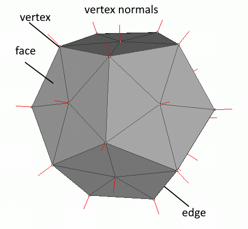
A mesh is a collection of vertices, edges, and faces. A line between two vertices is an edge, and a closed polygon is a face. The polygons can be triangles, quadrilaterals or any convex or concave polygon. Concave polygons are not allowed because they are not handled by OpenGL does not handle them (for better optimization). We prefer triangular meshes because they are simpler to optimize and render.
Meshes represent the surface and the volume of 3D objects. So, we use them in our 3D applications to draw our objects or to check for collisions.
The math library in the atlas engine is based on triangular mesh to represent any solid object. This simplifies drawing and unifies our calculations.
An eye to the word
Before we go any further we should have some basic understanding about the way OpenGL defines and handles what we see and how. As you might expect, starting with view definition in OpenGL is not that hard. This figure shows the view volume as defined in OpenGL.
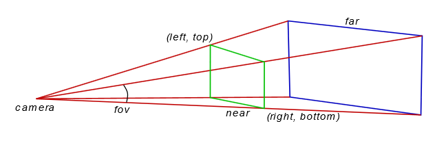
The camera is actually the position of the viewer. The field of view is a cone, but because the screen is rectangular it is cropped to form a pyramid. In OpenGL we must define the fov (field of view) angle, the aspect ratio of the width and height of the display window, the (left, top) and (right, bottom) points, the distance of the near plane (marked in green) and the distance of the far plane (blue). Anything closer to the viewer than the near plane, or further than the far plane is not rendered.
The geometric solid that defines the view volume is a frustum because it is part of a view cone (pyramid if we want to be precise). It is the shape of the computer screen that defines a pyramid, and this is the reason we talk about frustum but draw and calculate a pyramid.
The viewport projection matrix
The dimensions of the view window and the near and far distances are used to form what we call the frustum matrix or viewport matrix.
There is a function for this purpose in the math library. It is in the file cg_matrix.cpp and this is its prototype:
void frustum_matrix(cg_float* matrix, cg_float left, cg_float right, cg_float bottom, cg_float top, cg_float znear, cg_float zfar);The left-top and right-bottom points hardly make any sense to humans. We can better understand the angle indicating the field of view. This is a metric completely independent of the view distance. If you notice camera lenses and zoom are also measured by this angle. Focal length of a lens is actually a function of this angle.
The cg_viewport class which handles the viewport specifics.The graphics library has the function set_fov which sets this angle. Notice that the angle is in the vertical axis and not in the horizontal.
Having this angle, it is a matter of simple trigonometry to calculate the two corner points and build the transformation matrix for the projection.
The camera matrix
Setting the viewport is independent of the location we are standing, the direction we are looking at, and our orientation. These parameters are moving the view volume around bringing objects in and out of view.
We can use three vectors to handle the camera.
- The first vector will hold the actual location of the camera.
- The second the point we are targeting.
- The third will point to our UP direction.
All this is handled by the cg_camera class. It requires the three vectors we just described and returns us the corresponding transformation matrix.
The first thing we do when initializing the application is create a viewport and camera object to handle the way we see the world.
Shading things
As we saw in part 3 the best practice when drawing in OpenGL, is to exploit the GPU and use the pipeline writing some shaders.
The shaders we are going to use for the time being are quite simple. Our primary goal is to explain how to handle the basic transformations in three dimensions. Drawing a simple triangle as we did before is not enough to master OpenGL.
So, for our first real 3D drawing we are only using a vertex and a fragment shader. The first is used to calculate the transformations of the vertices and the second to set the drawing color.
The graphics library supports reading the shaders from external files and this is how we use them here.
These are quite simple shaders so we can go with OpenGL version 3.3.
// vertex shader
#version 330 core
// vertex position in local coordinates
layout(location = 0) in vec3 aPos;
// camera has the combined viewing matrix
uniform mat4 camera;
// model has the combined matrix of object position and orientation
uniform mat4 model;

void main() {
    // calculate final vertex position in the 3D space
    gl_Position = camera * model * vec4(aPos, 1);
}
The only thing we need to pay attention to is the vertex shader which calculates the final position of the vertex. The camera matrix is the combined projection matrix for the viewport and the camera. We pass a combined matrix for speed reasons. This shader is called for every vertex, and if the scene has many complex objects it will be called thousands of times. So, it is better to save a matrix multiplication and perform it only once instead doing it for every vertex.
mat4 cam_matrix = m_cam->perspective() * m_view->perspective();
m_shader->set_mat4("camera", cam_matrix);
Take a good look at the fragment shader. In this sample it is just setting the drawing color to white. Here is the point where most of the visual effects take place. It will get more complex as we add effects.
// fragment shader
#version 330 core
// drawing color for OpenGL to use
out vec4 color;
void main() {
    color = vec4(1, 1, 1, 1);
}
Creating a simple solid
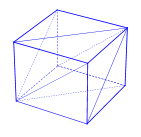
In the beginning we are going to create a cube and a sphere. The are among the simplest solids and they are very good to show animation and other techniques, like textures, shadows etc.
As mentioned earlier, the base of all solid objects is the mesh. When we create our objects the library generates a mesh. This mesh can be used later for all physics related calculations. But for the time being we will stick to the mesh and how to use it in OpenGL.
When we create a cg_gl_cube the graphics library creates a mesh to represent the cube. To accurately display a mesh, we need three things. The first element is the vertices of the mesh, the second element is the normal vector at each vertex and finally the order in which to access the vertices that represent the faces of the mesh and draw them. Our implementation contains one extra element the texture coordinates.
Normal vectors will be used later when we add lighting, and texture coordinates when we add textures. Right now, we are drawing in wireframe mode.
Solid objects can be moved and rotated. For this reason, they have two member variables of type vec3, the position and the rotation. We are using Euler angles for the rotation and not quaternions to keep things simple. In the frame_move function we move our objects. The function takes as input parameter the elapsed time since it was last called. In the first part we touched the subject of keeping track of time. As you can see in the code the elapsed time plays a significant role in the object movement as the amount of movement depends on it and the 'speed'. We change their angle around one or more axes. The cube is rotated around all three of its axes while the sphere is only rotated around its vertical axis.
Drawing the objects
In our frame_move function we moved our objects. The movements simply change the value of their internal variables. These values control their position and orientation in our virtual world. We must pass them to OpenGL to render them correctly.
virtual void frame_move(float fElapsed) {
    // rotate the objects
    simple_cube->rotate_by(vec3(dtr(fElapsed * 10), dtr(fElapsed * 20), dtr(fElapsed * 30)));
    simple_globe->rotate_by(vec3(0, dtr(fElapsed * 20), 0));

    simple_cube_t->rotate_by(vec3(dtr(fElapsed * 10), dtr(fElapsed * 20), dtr(fElapsed * 30)));
    simple_globe_t->rotate_by(vec3(0, dtr(fElapsed * 20), 0));
}
This is done in the frame_render function. First we create the camera matrix from the view and camera parameters. Then we activate the simple shader for wireframe drawing and draw our objects. This is all we care about for now. The rest will be covered in the next section.
virtual void frame_render() {
    // set the viewport to the whole window
    m_view->set_viewport();

    // clear screen
    glClearColor(.5f, .5f, .5f, 1.f);
    glClear(GL_COLOR_BUFFER_BIT | GL_DEPTH_BUFFER_BIT);

    // combine the view and camera matrices into one
    mat4 cam_matrix = m_cam->perspective() * m_view->perspective();

    // enable the shader
    m_shader->use();
    // set the combined view matrix
    m_shader->set_mat4("camera", cam_matrix);

    // draw the objects
    simple_cube->render(m_shader);
    simple_globe->render(m_shader);

    // enable the texture shader
    mt_shader->use();
    // set the combined view matrix
    mt_shader->set_mat4("camera", cam_matrix);

    // activate the texture engine
    glActiveTexture(GL_TEXTURE0);

    // draw the objects
    glBindTexture(GL_TEXTURE_2D, texture2);
    simple_cube_t->render(mt_shader);

    glBindTexture(GL_TEXTURE_2D, texture);
    simple_globe_t->render(mt_shader);
}
This is done in the cube render function. We start by calculating the object matrix. This is the product of the translation, rotation and scale matrix. Matrix multiplication is not commutative so we must keep this order when we calculate our object matrix. Then we pass this matrix to the shader and draw our mesh.
virtual void render(cg_shader* _shader) {
    if (!vao) return;

    // position object
    mat4 ob_matrix = tmat * rmat * smat;
    // pass transformation to shader
    _shader->set_mat4("model", ob_matrix);
    glBindVertexArray(vao);
    if (draw_elements)
    {
        // setup drawing
        glFrontFace(GL_CCW);
        glPolygonMode(GL_FRONT, draw_mode);
        glDrawElements(GL_TRIANGLES, (unsigned int)m_mesh_data->indices.size(), GL_UNSIGNED_SHORT, 0);
    }
    else
    {
        // setup drawing
        glPatchParameteri(GL_PATCH_VERTICES, 4);
        glPolygonMode(GL_FRONT_AND_BACK, draw_mode);
        glDrawArrays(GL_PATCHES, 0, (unsigned int)m_mesh_data->indices.size());
    }
    glBindVertexArray(0);
}
Adding textures
Realistic 3D environments, especially in games, are based on illusions. Illusions generated by images. These are the textures applied on surfaces. It is a lot easier, and faster, to use the image of a complicated object, instead of drawing its geometry. Take for example the tire of a car. The tread is complex, and drawing requires a lot of graphics memory to store the geometry and GPU power to process it.

Now suppose we want to draw the earth rotating to show the change between day and night. Can you imagine the amount of data required to represent the earth's surface? If we apply a good image of the earth showing the continents and the sea on a simple sphere, we can create the illusion of the earth. We can then rotate the sphere any way we want and get a good view of the earth from any point of view we want.
We start by creating a sphere. Just like the cube, our little 3D engine has a sphere object built in. The process of creating a sphere is simple. We just call new to create an instance of the cg_gl_sphere class, which takes care of the mesh generation and all the vertex buffers and vertex arrays.
The difference from the wireframe drawing we saw before is in the shaders. Instead of supplying a simple color to the rendering engine of the OpenGL it reads the texture image and feeds the renderer with the appropriate color from it.
Textures are data that we store in the GPU memory. They are used to add detail to our objects. Here we focus on images that we wrap around the objects to give them the illusion of detail.
We load an image file, only targa images are supported, by calling the load_texture function, which returns us the texture ID on success, or -1 on failure.
Textures are like vertex buffers. We must generate them, a.k.a. allocate storage for them, and then bind them to apply any operations on them, like we do with vertex buffers.
GLuint load_texture(const char* fname) {
    GLuint tex = -1; // default return is failure

    cg_image img;    // try to load the TGA image
    if (!img.load(fname))
	     return tex;   // return failure (invalid OpenGL id)

    // how bytes are aligned in memory
    glPixelStorei(GL_UNPACK_ALIGNMENT, 1);
    // enable textures for the following commands
    glEnable(GL_TEXTURE_2D);

    // we will generate a texture with mipmaps
    glTexParameteri(GL_TEXTURE_2D, GL_GENERATE_MIPMAP, GL_TRUE);
    // generate texture
    glGenTextures(1, &tex);
    // and make it the current processing object
    glBindTexture(GL_TEXTURE_2D, tex);

    // how texture values (colors) are interpreted
    glTexEnvf(GL_TEXTURE_ENV, GL_TEXTURE_ENV_MODE, GL_MODULATE);
    // when texture area is small, bilinear filter the closest mipmap
    glTexParameterf(GL_TEXTURE_2D, GL_TEXTURE_MIN_FILTER, GL_LINEAR_MIPMAP_NEAREST);
    // when texture area is large, bilinear filter the original
    glTexParameterf(GL_TEXTURE_2D, GL_TEXTURE_MAG_FILTER, GL_LINEAR);

    // the texture wraps over at the edges (repeat)
    glTexParameterf(GL_TEXTURE_2D, GL_TEXTURE_WRAP_S, GL_REPEAT);
    glTexParameterf(GL_TEXTURE_2D, GL_TEXTURE_WRAP_T, GL_REPEAT);
    // now build the mipmaps
    gluBuild2DMipmaps(GL_TEXTURE_2D, 4, img.get_width(), img.get_height(),
	     img.get_image_format(), img.get_data_type(), img.get_image());
    glBindTexture(GL_TEXTURE_2D, 0);
    img.release();// release the TGA image

    return tex;
}
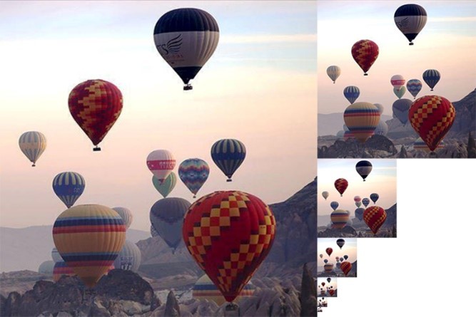
After we setup the memory alignment, we enable the use of textures, and we declare the textures to have mipmaps. Mipmaps are precalculated images, each of which is in lower resolution than the previous.
The image shows a mipmap image. This image contains copies of progressively lower resolution of the original image. Using mipmaps allows OpenGL to use predefined images of lower resolution when needed instead of resampling the original image every time.
OpenGL can generate images like this when loading an image and use them when needed.
Then we generate and bind the texture so that all subsequent calls will act upon it. For our needs we set up our bitmaps to use the closest mipmap image and to repeat the texture when needed. Now that we are done parametrizing OpenGL we pass the image data and invoke the mipmap building engine.
When all is done we unbind the texture and release the image. The image data needed are now stored in the graphics card.
Mapping the texture

The texture was loaded into the GPU memory but how can we map the texture to the object? There must be some mapping between the image and the surface of our object. There must be some way we can tell OpenGL how to draw using colors from the image.
Here is how OpenGL addresses the problem. First the texture is given coordinates from 0 to 1 in each direction, as we see in this figure. Then we can assign an s and t (for horizontal and vertical) between 0 and 1, to each vertex of our mesh. A simplified mapping of an image on a simple mesh is shown in Figure 6.
When it renders the image it samples according to these coordinates to color the vertices and it interpolates for the image coordinates corresponding to the rest of the triangles surface.
Sampling the image
The sampling of the image is done in the fragment shader. There we read the pixel from the image and pass it to OpenGL to finally draw. But there are some things that must be done before that.
It all starts with the frame_render function, which takes care of all our drawing. First we enable the shader we have written for this purpose and we set the camera matrix. Then we enable textured drawing, activate the object texture and draw the object. Here is the code fragment from the frame_render function.
// enable the texture shader
mt_shader->use();
// set the combined view matrix
mt_shader->set_mat4("camera", cam_matrix);

// activate texture draw
glActiveTexture(GL_TEXTURE0);

// set the active texture
glBindTexture(GL_TEXTURE_2D, texture_cube);
// and draw
simple_cube_t->render(mt_shader);
The vertex shader apart from setting the vertex coordinates has one more job to do. It reads the texture coordinates of the vertex and passes them to the fragment shader. The fragment shader then uses these coordinates to read the color data from the texture image and pass that value to OpenGL.
// vertex shader
#version 330 core
// vertex position in local coordinates
layout(location = 0) in vec3 aPos;
// the texture coordinates
layout(location = 2) in vec2 aTexCoord;
// texture coordinate output for fragment shader
out vec2 texCoord;
// camera has the combined viewing matrix
uniform mat4 camera;
// model has the combined matrix of object position and orientation
uniform mat4 model;
void main() {
    // calculate final vertex position in the 3D space
    gl_Position = camera * model * vec4(aPos, 1);
    texCoord = aTexCoord;
}
// fragment shader
#version 330 core
// the texture coordinate
in vec2 texCoord;
// the image we take samples from
uniform sampler2D textureSampler;
// drawing color for OpenGL to use
out vec4 color;
void main() {
    color = vec4(texture(textureSampler, texCoord).rgb,1);
}
Now there is only one thing left to clear. Where do we find this image we sample from? This is done by binding the texture right before we call the sphere to render itself. The texture sampler accesses the last texture that was bound.
Summary
In this part
- We were introduced to the atlas engine that we are going to use from now on.
- We saw how the atlas engine creates simple 3D objects like cubes and spheres.
- We were introduced to some simple animation.
- Finally, we brought some life to our objects using textures.