Introduction to OpenGL
Part 2: The pipeline
Modern graphics hardware is immensely powerful and massively parallel. This means that they can perform too many operations per unit of time. All this results in spectacular images in real time. Our games and animations can use all this power and give users a memorable experience.
By organizing our data and the order of operations we can take advantage of the available hardware and maximize its efficiency. We can break, for instance, the job into distinct stages, and then execute the operations in each one in parallel.
This serialization of stages is what OpenGL does to generate the images we see. For added convenience most of these stages are programmable. We can write our own code that will run on the GPU for maximum efficiency and have complete control over the result.
Walk the pipeline
There are certain steps in the process of generating OpenGL output. We have access to a number of them. Our main tool is the GL Shading Language, or GLSL for short. Some are fixed processes carried by the system. Here is a brief description of the OpenGL pipeline:
- Vertex Specification: The first thing we must do when we program in OpenGL, is to collect our data. An object on the screen is made up of certain attributes. These are the vertices, a.k.a. the points, the edges, and the faces they define, the colors and the textures, or any other attributes we may need.
- Vertex Shader: The first actual calculation is the Vertex Shader. The information we collected in the previous step passes through this. The objective of this step is to calculate the final position of every vertex in the scene. This is a good place to put our 3D calculations, since the GPU will execute them.
- Tessellation: in this step the primitives are divided into a smoother mesh of triangles. This step is optional.
- Geometry Shader: In this step we can further manipulate our primitives. We can break them into smaller ones, organize them differently i.e., convert points to triangles, or even remove some of them. This step is also optional.
- Vertex Post Processing: In this stage, OpenGL decides what is in our field of view and what is not. This process is called clipping. There is no way we can intervene in this stage.
- Primitive Assembly: This stage collects the vertex data into an ordered sequence of simple primitives. It is also an internal stage we cannot modify.
- Rasterization: This stage creates fragments. It is a particularly important step of the pipeline.
- Fragment Shader: This stage calculates the color of each fragment calculated by the previous step. We can write code in GLSL and manipulate what the user sees. It is optional to do so, but taking in mind the advantages it gives us, it is clear that this is a very good point to add our code.
- Per-Sample Operations: This is the last step of the pipeline. In this stage the engine performs some final tests like Stencil Test, Depth Test or Scissor Test.
One step at a time
In the previous part we saw a sample program that was throwing some drawing commands to OpenGL. It was a very straight forward and simple solution. On the other hand, looking at the description of the pipeline can be quite intimidating. It is a lot of work that must be done to draw a simple triangle on the screen.
This is true, but the benefits are a good compensation. Keeping our renderings organized in the way directed by the pipeline results in a much faster program in general. The draw data are stored in the video memory for faster access and the GPU performs most of the calculations in parallel.
Structure of the program
In the sample program pipeline, we see a first approach of creating a reusable infrastructure for our games. This will take away a lot of the work in the future as more code will be added to this library.
This program copies the code from the previous example. Window and OpenGL initialization are the same. The program is now made up of two files. In the first file called common.cpp we can see the code used for window and library initialization, as well as the WinMain function. This code is our first library code. It is code we do not need to change very often.
We may have to add some bits here and there to support our increasing needs. For our current needs I have added the functions init_game and terminate_game. The first is called before we enter the main loop, so we can do our app specific initialization and the second is called after the main loop to perform any cleanup we need to do.
Organizing the data
The first step in the pipeline is the Vertex Specification. In this step we gather and organize the data that represent our meshes and models, and we load our shader programs.
This is done in our new init_game function. There, the first thing we do is load the shaders into the GPU memory. These little programs will guide the GPU when we render our scene.
Then we allocate space in the memory of our graphics card and store the triangle geometry and color attributes to be used for drawing. We are starting with the geometry data. We will explain everything about the shaders a little later. For the time being, we compile and load them to get things going.
The first thing we must do is allocate a Vertex Array in which we will store our data.
// create the main storage
glGenVertexArrays(1, &vertex_array);
// bind and use it
glBindVertexArray(vertex_array);
glGenVertexArrays allocates the memory and stores its identifier in the vertex_array variable. OpenGL depends heavily on its state. After we allocate the array, we bind it using glBindVertexArray. From that point on subsequent calls are appended to this array. Any other allocations are stored within this array. So, our next step which allocates memory for the vertices of our triangle will allocate the buffer inside the vertex_array.
// create a buffer for the vertices
glGenBuffers(1, &vertex_buffer);
glBindBuffer(GL_ARRAY_BUFFER, vertex_buffer);
glBufferData(GL_ARRAY_BUFFER, sizeof(vertices), vertices, GL_STATIC_DRAW);
glVertexAttribPointer(0, 3, GL_FLOAT, GL_FALSE, 0, (void*)0);
glEnableVertexAttribArray(0);
This allocated buffer is inside the vertex array and after we bind it glBufferData copies the vertex coordinates inside the vertex_buffer.
OpenGL buffers can contain more than just data. They can also store commands like glVertexAttribPointer which instructs the library where to ‘find’ the data. Storing these commands within the vertex buffers speeds the drawing process dramatically. You can visualize the buffers as programs containing both data and code that are stored in superfast GPU memory and run on the GPU as well.
Similarly to the vertex data we allocate buffer for the colors. We can add buffers containing any information we like. The most common attributes are colors, textures coordinates and normal vectors.
The Shaders
Now we are going to focus on the Shaders. Those little black boxes we have placed in the pipeline.
Vertex shader
As we know from everyday experience, what we see is subject to our location, the direction of our sight, the objects’ location, and orientation. On the other hand, every object can have its own coordinate system and its own geometry, expressed on that system.
This is the way we define objects in 3D handling software, be it Computer Aided Design or Physics simulation software, including video games, or any other kind of software of which we can think.
It is the responsibility of the Vertex Shader to translate the local coordinates of the vertices to real world coordinates and then to view coordinates, so that they are correctly put in the 'world' and drawn.
The shader can take as input the transformation matrices for the view and for the objects along with the coordinates and other attributes of the vertices. The transformation matrices and the coordinates are used to calculate the final location of the vertices on the screen. Here is the sample shader:
#version 410 core
// input to the vertex shader
// location where the vertex coordinates are stored
layout(location = 0) in vec3 aPos;
// location where the vertex color is stored
layout(location = 1) in vec3 aCol;
// 4x4 matrix for the model
uniform mat4 model;
// 4x4 matrix with the view parameters
uniform mat4 view;

// output of the vertex shader
// the vertex color is passed to the fragment shader
out vec4 vs_color;

// 'main' the entry point to the shader
void main(){
    // calculate the final position for the vertex
    gl_Position = view * model * vec4(aPos, 1.0);
    // the vertex color
    vs_color = vec4(aCol, 1.0);
}
The first line defines the minimum OpenGL version requirement, which is 4.1 in this case.
Then we describe how our vertex array is organized. The first buffer contains the vertices in a three-dimensional vector, and the second contains the colors again as three-dimensional vectors.
The next two variables are the transformation matrices to use. One for the model positioning and orientation, and one for the camera transformation.
Finally, we define our output variable vs_color that we are going to use so we can pass the user color to the fragment shader. More on shader when its time comes. Now let us focus on what vertex shader does.
OpenGL has some built in variables we can set. One such variable is gl_Position. In this variable we set the final position of the vertex. Here we multiply the view matrix with model matrix and the vertex position. The matrices must be organized column major because this is the convention in OpenGL.
The final variable we set is vs_color which is used to read the color from the vertex attributes and pass it to the next step.
In our program we introduced some new code to handle our requirements in mathematics. The code is in the math.h file. the first thing we introduced is the 4x4 matrix. We need this for the transformations we are going to use in this sample.
mat4 view = perspective_matrix(pi / 4.f, (float)(g_window.vwidth) / (float)(g_window.vheight), 1.f, 1000.f);
mat4 model = translation_matrix(0,0,-6);

// use shader
glUseProgram(shaderID);
set_mat4(shaderID, "model", (cg_float*)model);
set_mat4(shaderID, "view", (cg_float*)view);
// draw the triangle (vertex coordinates are in the shader)
glBindVertexArray(vertex_array);
glPolygonMode(GL_FRONT_AND_BACK, GL_FILL);
glDrawArrays(GL_TRIANGLES, 0, 3);
glBindVertexArray(0);
The first matrix represents the camera like the call to gluPerspective we saw in the previous example, and the second is the translation matrix which is equivalent to the glTranslatef call. We pass these matrices to the shader, before we start drawing, giving them the variable names we earlier in the shader.
Fast forward to the Fragment Shader
Now we are going to skip a step or two and jump directly to the Fragment Shader. This will let us see how to draw a colorful triangle like the previous example. As we see in the paragraph above. we just set the transformation matrices and then ask OpenGL to draw. Here is the Fragment Shader.
#version 410 core
out vec4 color;
in vec4 vs_color;
void main(){
    color = vs_color;
}
The output of this shader step is the color OpenGL can use for the fragment. So, we just declare an output variable and we call it color. Now remember the vs_color variable we declared as the output of the vertex shader. Here we declare the same variable, only this time it is an input variable. So, we read the color passed to us by the vertex shader and then we pass it to OpenGL. We need to do this because only the vertex shader has access to the vertex array and its contents.
Tessellation
Tessellation is the process of breaking up a large area into smaller pieces. This is what we do when we apply small tiles on a large surface. In computer graphics we divide a large polygon, usually a triangle, into smaller ones.
This process is particularly useful when we want to apply higher detail to objects that are closer to the viewer, while those that are further away do not need high detailed drawing.
Tessellation follows the vertex shader, and it is done in three steps:
The first of the three tessellation phases is the tessellation control shader. This shader takes its input from the vertex shader and is primarily responsible for two things: the determination of the level of tessellation that will be sent to the tessellation engine, and the generation of data that will be sent to the tessellation evaluation shader that is run after tessellation has occurred.
Second is the Tessellation Engine that generates the new vertices. It is a fixed function engine, and we can only set its parameters in the tessellation control shader. it produces a number of output vertices representing the primitives it has generated. These are passed to the tessellation evaluation shader.
Third and last step of the process is the tessellation evaluation shader. The tessellation evaluation shader runs an invocation for each vertex produced by the tessellation engine. When the tessellation levels are high, the tessellation evaluation shader could run an extremely substantial number of times. For this reason, you should be careful with complex evaluation shaders and high tessellation levels.
Starting, we create a simpler vertex shader. The new one just reads the model coordinates and passes them in the OpenGL variable gl_Position. The view and model matrices will be applied in the last step of tessellation evaluation.
#version 410 core
layout(location = 0) in vec3 aPos;
void main(){
    gl_Position = vec4(aPos, 1.0);
}
Here are two simple shaders that we can use to tessellate a simple triangle. First is the control shader:
// first is the control shader
#version 410 core
layout(vertices = 3) out;
void main(void)
{
    if (gl_InvocationID == 0)
    {
        gl_TessLevelInner[0] = 3.0;
        // number of tessellations on each of the outer edges
        gl_TessLevelOuter[0] = 3.0;
        gl_TessLevelOuter[1] = 3.0;
        gl_TessLevelOuter[2] = 3.0;
    }
    gl_out[gl_InvocationID].gl_Position = gl_in[gl_InvocationID].gl_Position;
}
And second the evaluation shader:
// second is the evaluation shader
#version 410 core
layout(triangles, equal_spacing, cw) in;
uniform mat4 model;
uniform mat4 view;
out vec4 es_color;
void main(void)
{
    vec4 pos = (gl_TessCoord.x * gl_in[0].gl_Position) +
        (gl_TessCoord.y * gl_in[1].gl_Position) +
        (gl_TessCoord.z * gl_in[2].gl_Position);
    es_color = vec4(gl_TessCoord,1);
    gl_Position = view*model*pos;
}
Finally, the Fragment Shader
OpenGL has finished rasterizing the image. That means the image is ready pixel by pixel. It knows what each pixel on the screen represents in terms of objects depth and orientation. This is our last chance, based on knowing what we need to draw, to tell OpenGL what color to set for each pixel.
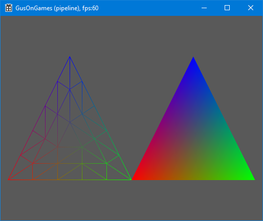
We created a fragment shader before talking about tessellation. There we set the pixel color. Now we are asked to set the pixel color for a tessellated object. For this reason, we calculated the color in the evaluation shader. There we had access to the coordinates generated by the tessellation engine. We used that information to calculate a color and create a fancy result.
#version 410 core
out vec4 color;
in vec4 es_color;
void main(void) {
    color = es_color;
}
Summary
In this part we saw the steps of the rendering pipeline. It is important to understand how the pipeline works and utilize it to the maximum to get the best results both in image quality and speed of execution.
Here are the steps of the pipeline once again:
- Vertex specification
- Vertex shader
- Tessellation
- Geometry shader
- Vertex post processing
- Primitive assembly
- Rasterization
- Fragment shader.
- Per-sample operations